Greetings! Here are my notes for how I used a 3018 CNC machine on the mac. I had two primary methods that I tried. One was using a .BRD import workflow for Chilipeppr, and the other way was to use a free Carbide 3d web tool to generate the copper trace toolpaths. Chilipeppr runs the gcode in both methods.
1. Chilipeppr Direct .brd Import Workflow
Chilipeppr Direct .brd Import Workflow
Generate gcode using Chilipeppr
The only thing you should really be watching out for is the routing depth. Make sure it goes below the surface of the board.
Run the gcode using Chilipeppr
whoa there, let’s talk
here’s where the other half of the situation happens. We have the idea, the breadboard prototype, eagle cad designs, we have the gerbers, xcellon, and now we have gcode. Now we enter the physical world.
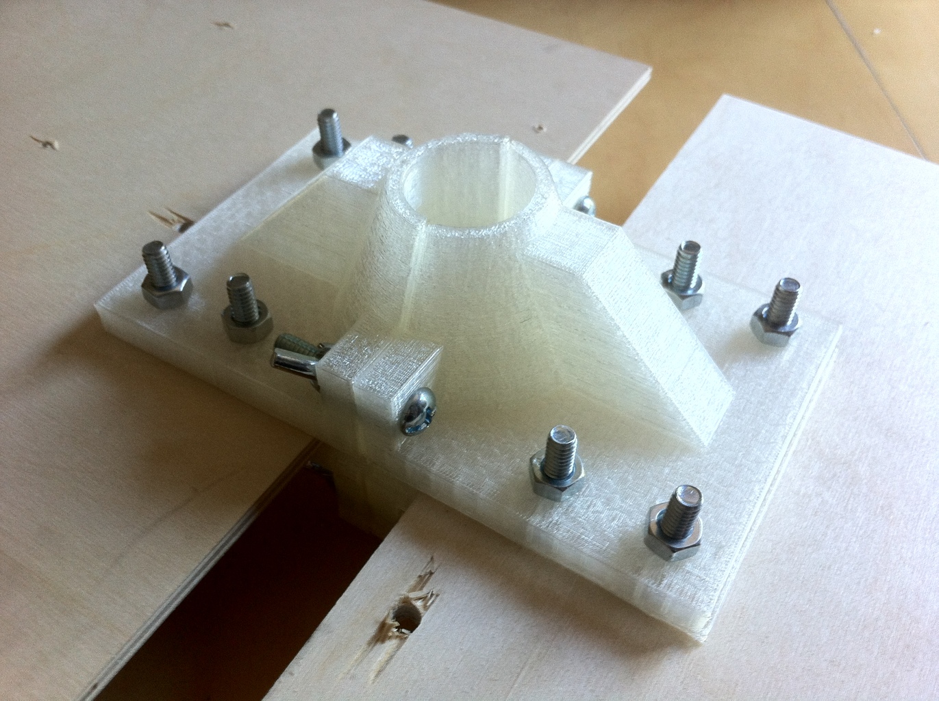
machine physical setup
the 3018 isn’t exactly loud, but it could be quieter. I have spare discs of silicone hanging around, so I’ve cut some up to make rubber pads to go underneath the machine. You could easily just implement LRF† support instead.
† little rubber feet
With the machine facing you, the x axis runs left to right with the yz support frame being further away from you. This will make understanding the machine’s movement easier when we get to later steps in The Workflow.
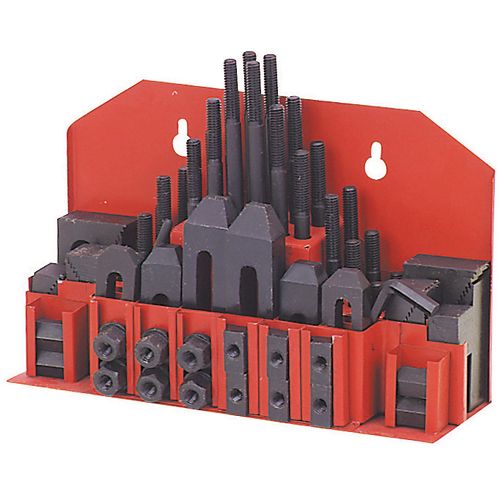
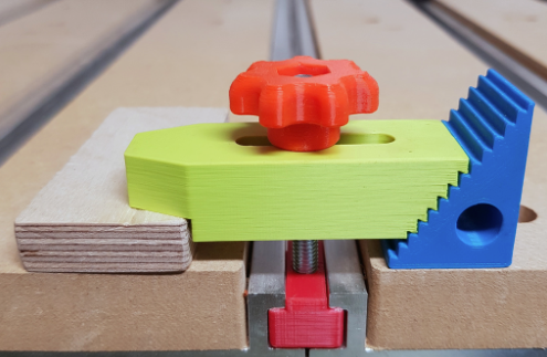
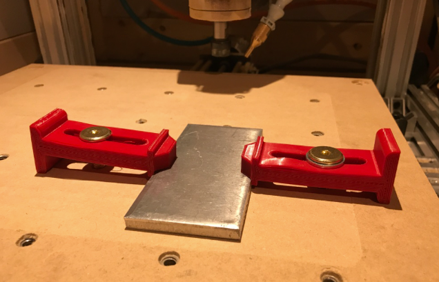
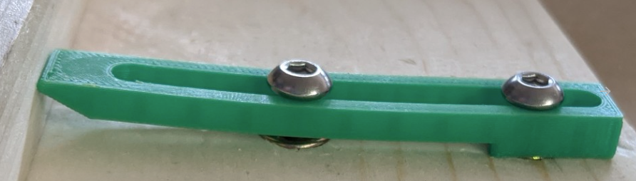
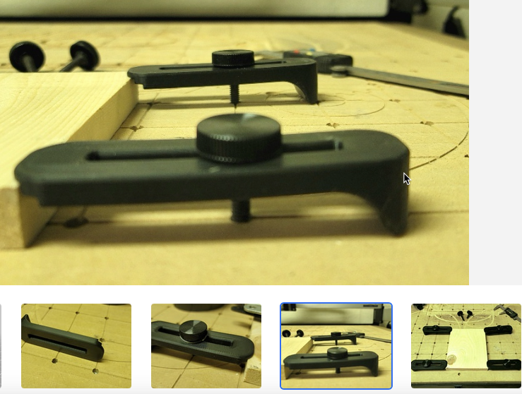
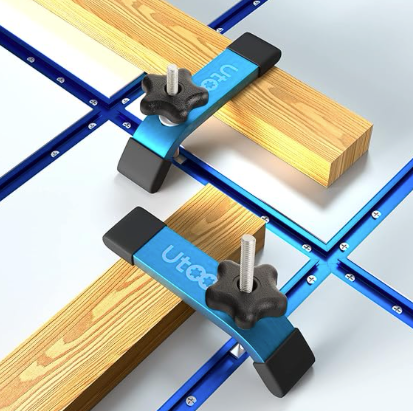
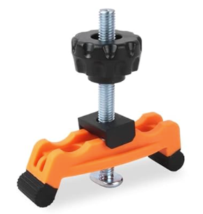
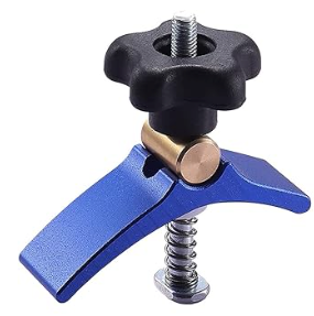
double sided tape / hold down options
Without a doubt, I prefer the super-glue’d blue painters tape trick, as described by this straight up wizard.
spoil board
I’m using a sheet of ~1/4″ thick acrylic, because I have a ton of that sitting idle, but it’s not too important what you use. You’re goingt to be robotically drilling holes, and lots of them, so use some kind of spoil board so you don’t drill into the aluminum bed of the machine.
Use some diy double sided tape to stick the spoil board to the aluminum bed of the machine.
single sided copper laminate
I got mine from aliexpress at about $5 a sheet for ~7″x11″ (200mm x 300mm)
thoughts on placement of the copper on the 3018
You’ll want to have a bit of overhang of the copper board exposed off the bed of the machine, in order to attach the aligator clips for the upcoming autoleveling step.
drag and drop the .brd file into chilipeppr.com/grbl
The tool paths should show up in a 3d environment in the web browser. Running gcode inside of a web browser. *welcome… to the world of tomorrow*
autolevelling
This is not an optional step! All copper clad boards are not-flat, and because of the extremely shallow depth of cut we’ll be making, we need to have the toolpaths be calibrated to follow the curve of the board.
On the 3018 CNC machine, the probe pin is #5 in the mostly-unused expansion pins in the back. There are two, and you need both. One is the signal, and the other is ground. When you run autoleveling, you attach one aligator clip to the copper, and the other to your endmill. Then the program will run a bunch of tests to see how un-flat your copper board is.
specific settings
probe feed rate: 80max negative z: -3z final safety height: 35
sending autoleveled gcode to workspace
Click on the button after the autoleveling routing finishes to have it fix your toolpaths to use the contour of your copper clad board.
Finally! Run trace isolation with v-bit endmill
tbd
Run drills with drill bit
tbd
Cut out the board with the bandsaw/
tbd
use like 220 grit sandpaper to knock the burrs down
tbd
vacuum the dust up FFS!
tbd
Test the board
seriously, just test it out for continuity before you put parts in it. Use a multimeter on the beep setting and just go around the board and see if every lead goes where it’s supposed to, can beep at the start and end of each lead, and make sure that no leads connect to any unexpected places.
solder the parts in
tbd
maybe test again
make sure after you soldered parts in that you didn’t accidentally bridge anything that you weren’t supposed to.
Eyyy, now you can write the specific arduino code
sometime things change, or you think of some optimizations between the breadboard and circuit board. Shit happens. Make sure your prototype code takes all those things into account.
fire that shit up
Did it burn anything out? Hopefully not!
2. Carbide 3d Workflow
export Gerbers
Gerber RS274X with the following layers and config options:
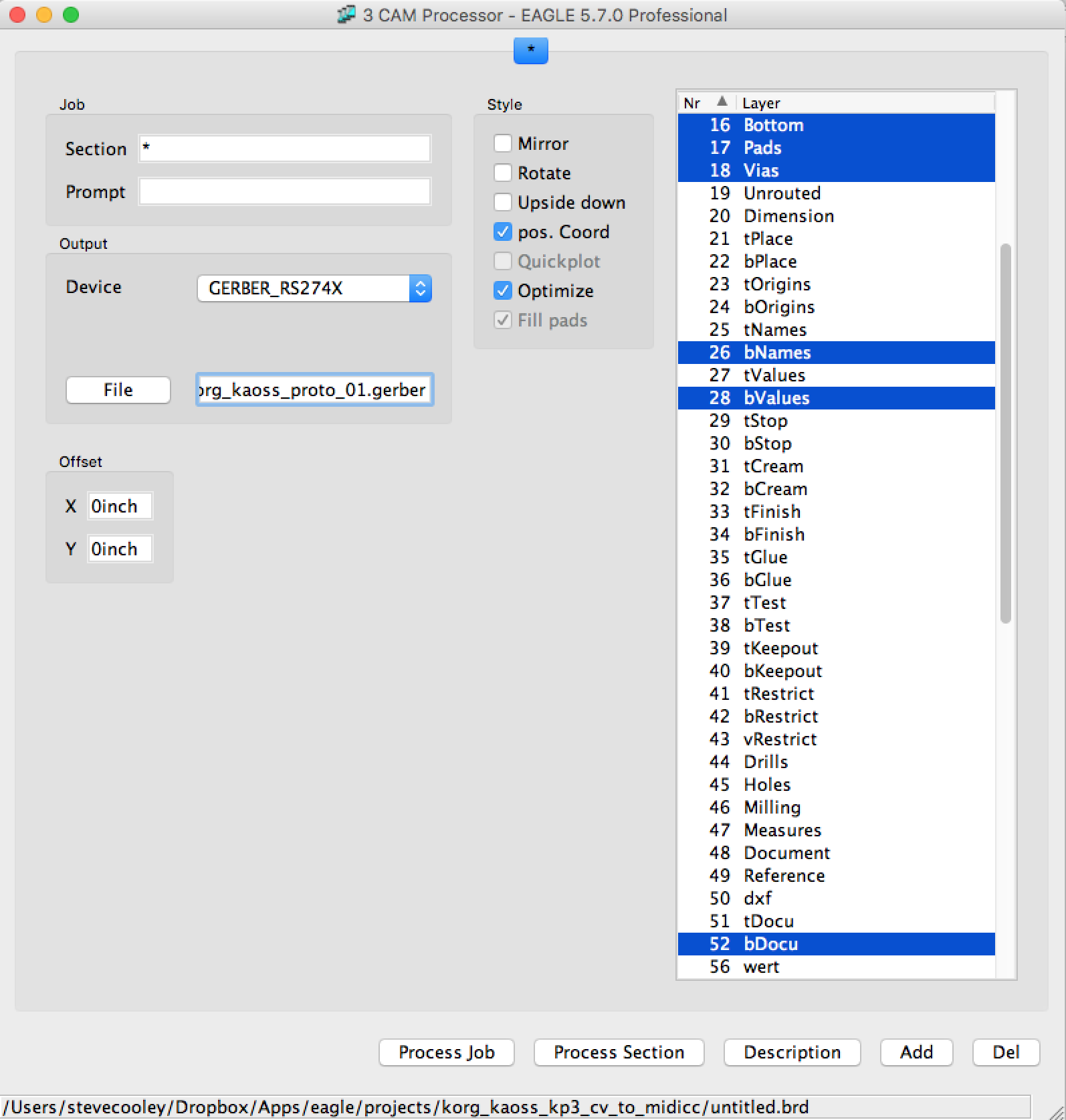
- Note that if you’re doing just the bottom layer, you should not check the
Mirroroption. It mirrors the layout for you automagically. I don’t actually know what thepos. CoordorOptimizeoptions do. - Note that I’ve named the file with
.gerberas the extension. The export process will also create some other files, and it’s confusing if you don’t know what it’s doing, like me, so I’ve decided to explicitly indicate what I want the extension to be so that I know exactly which file it is. Don’t assume it will do something intelligent with the correct file extension for gerbers. It does not know what you expect unless you tell it.
export excellon
Exactly the same as above, except for these layers:
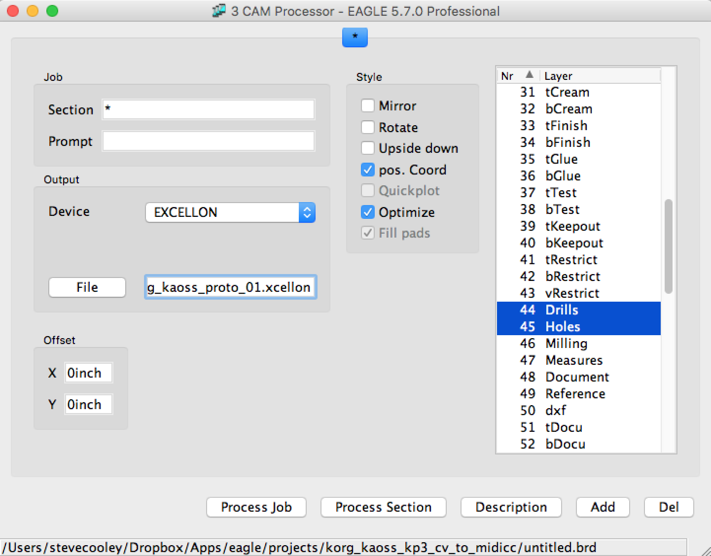
- Note that I’ve explicitly called for
.xcellonto be the file extension so that I know exactly which file it is.
Generate gcode from board
PCB-GCODE
http://www.pcbgcode.com/ stopped working for me with high sierra 10.13.5 🙁 so I found this next thing.
carbide3d.com
needs Gerber RS274X and Excellon files.
Looks like this for gerber options:
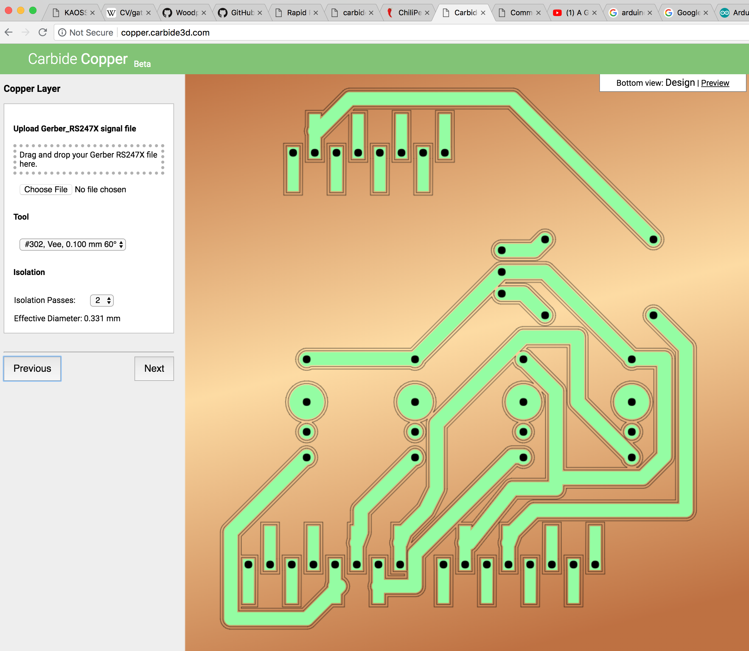
and this for Excellon
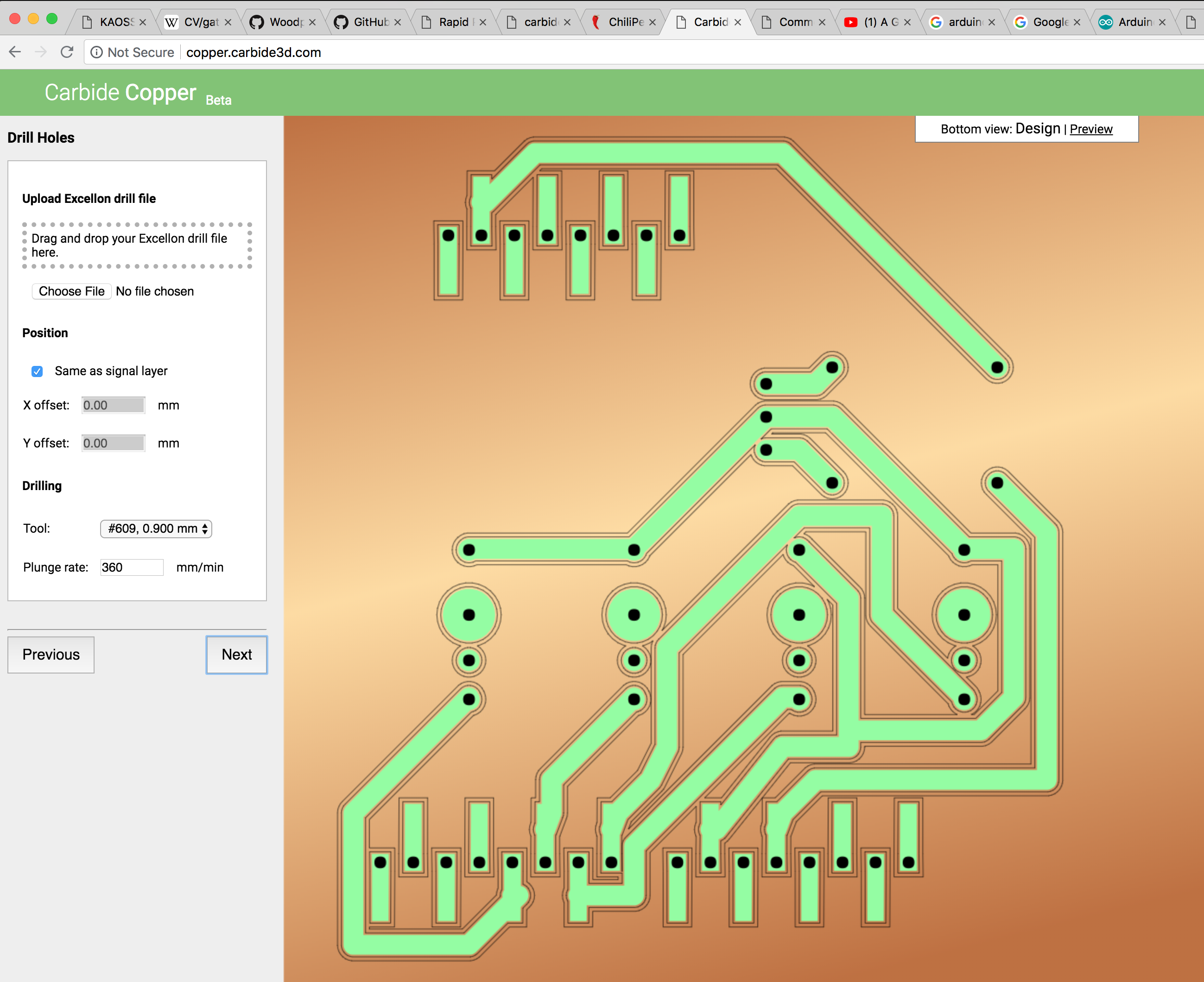
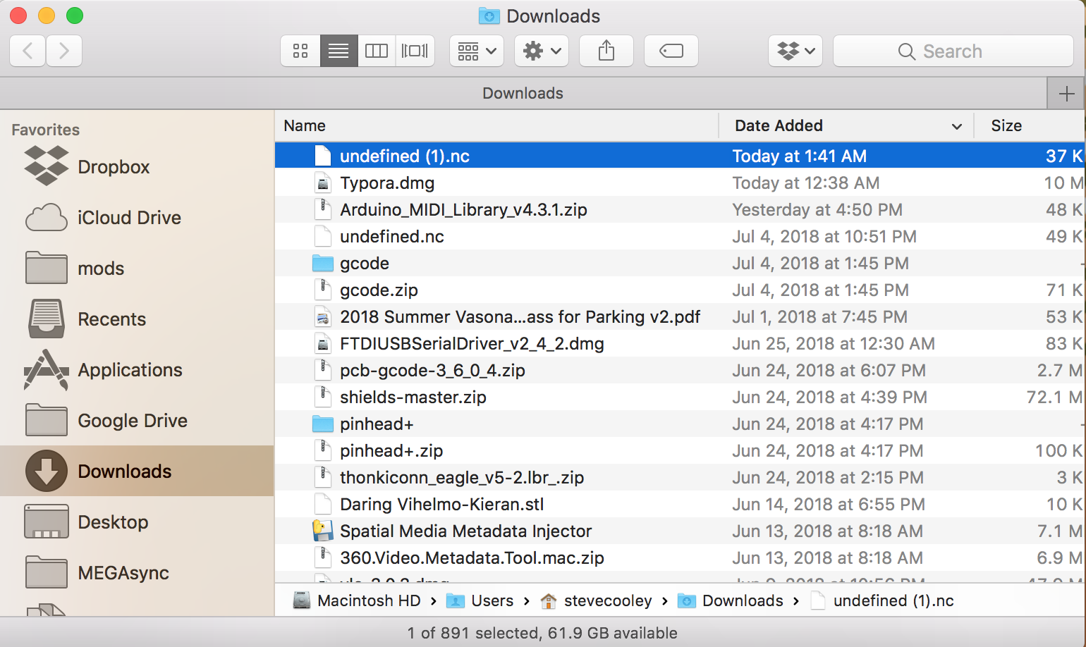
Exports a .nc file
Run the gcode using Chilipeppr
whoa there, let’s talk
here’s where the other half of the situation happens. We have the idea, the breadboard prototype, eagle cad designs, we have the gerbers, xcellon, and now we have gcode. Now we enter the physical world.
machine physical setup
the 3018 isn’t exactly loud, but it could be quieter. I have spare discs of silicone hanging around, so I’ve cut some up to make rubber pads to go underneath the machine. You could easily just implement LRF† support instead.
† little rubber feet
With the machine facing you, the x axis runs left to right with the yz support frame being further away from you. This will make understanding the machine’s movement easier when we get to later steps in The Workflow.
double sided tape / hold down options
Without a doubt, I prefer the super-glue’d blue painters tape trick, as described by this straight up wizard.
spoil board
I’m using a sheet of ~1/4″ thick acrylic, because I have a ton of that sitting idle, but it’s not too important what you use. You’re goingt to be robotically drilling holes, and lots of them, so use some kind of spoil board so you don’t drill into the aluminum bed of the machine.
Use some diy double sided tape to stick the spoil board to the aluminum bed of the machine.
single sided copper laminate
I got mine from aliexpress at about $5 a sheet for ~7″x11″ (200mm x 300mm)
thoughts on placement of the copper on the 3018
You’ll want to have a bit of overhang of the copper board exposed off the bed of the machine, in order to attach the aligator clips for the upcoming autoleveling step.
drag and drop the gcode file into chilipeppr.com/grbl
The tool paths should show up in a 3d environment in the web browser. Running gcode inside of a web browser. *welcome… to the world of tomorrow*
autolevelling
This is not an optional step! All copper clad boards are not-flat, and because of the extremely shallow depth of cut we’ll be making, we need to have the toolpaths be calibrated to follow the curve of the board.
On the 3018 CNC machine, the probe pin is #5 in the mostly-unused expansion pins in the back. There are two, and you need both. One is the signal, and the other is ground. When you run autoleveling, you attach one aligator clip to the copper, and the other to your endmill. Then the program will run a bunch of tests to see how un-flat your copper board is.
specific settings
probe feed rate: 80max negative z: -3z final safety height: 35
sending autoleveled gcode to workspace
Click on the button after the autoleveling routing finishes to have it fix your toolpaths to use the contour of your copper clad board.
Finally! Run trace isolation with v-bit endmill
tbd
Run drills with drill bit
tbd
Cut out the board with the bandsaw
tbd
use like 220 grit sandpaper to knock the burrs down
tbd
vacuum the dust up FFS!
tbd
Test the board
seriously, just test it out for continuity before you put parts in it. Use a multimeter on the beep setting and just go around the board and see if every lead goes where it’s supposed to, can beep at the start and end of each lead, and make sure that no leads connect to any unexpected places.
solder the parts in
tbd
maybe test again
make sure after you soldered parts in that you didn’t accidentally bridge anything that you weren’t supposed to.
Eyyy, now you can write the specific arduino code
sometime things change, or you think of some optimizations between the breadboard and circuit board. Shit happens. Make sure your prototype code takes all those things into account.
fire that shit up
Did it burn anything out? Hopefully not!